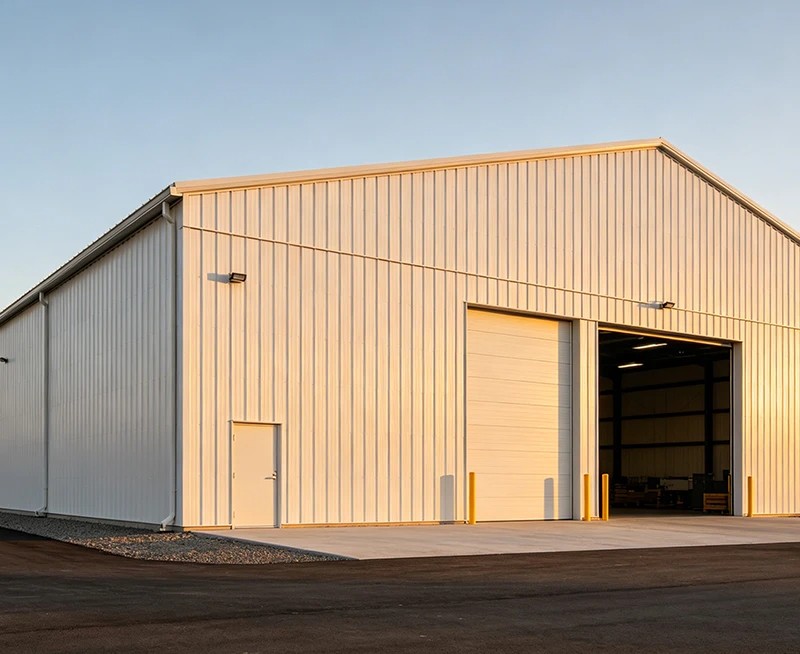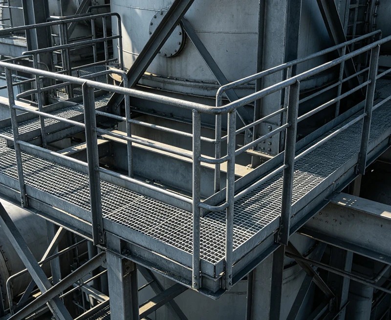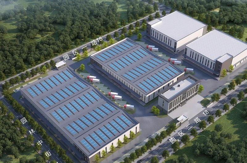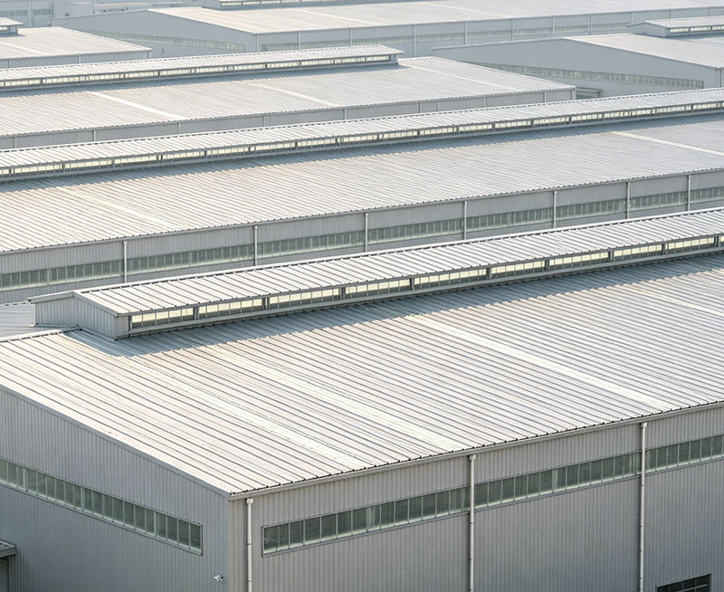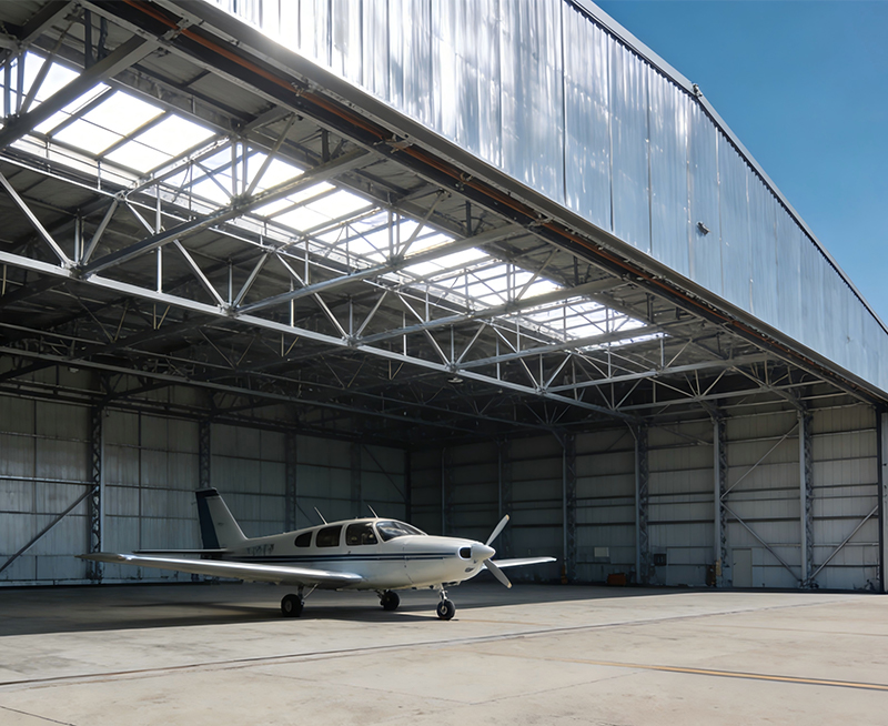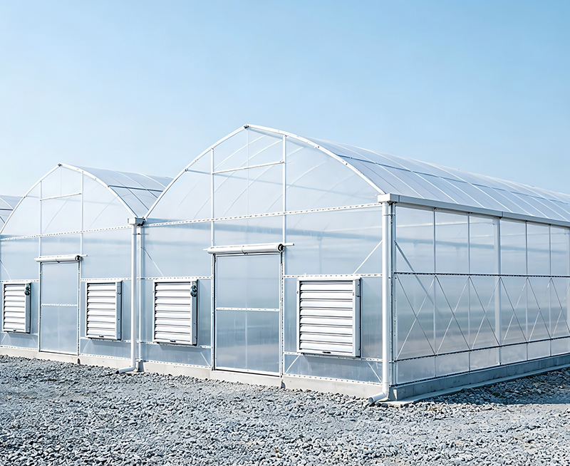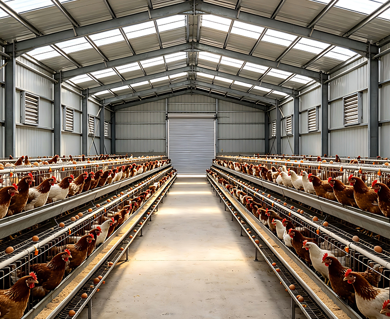




Large span steel structure design must balance clear space, safety, cost, and fast construction. A reliable project normally combines a steel space frame, structural analysis, and wind load assessment from the first design stage. For warehouses, sports halls, aircraft hangars, exhibition centers, and industrial plants, the correct system can cover spans from 30 to more than 100 meters without interior columns.
The main engineering challenge is not simply choosing larger steel members. Designers must control deflection, vibration, buckling, connection forces, fire performance, and erection risk as one system. This guide explains the key checks in simple terms and shows how overseas buyers can compare design options before placing an order.

1. Define the Project Loads Before Selecting the Structure
Every long-span steel building starts with a clear load plan. Loads are forces that the structure must carry during its service life. If the project data is incomplete, the design may be too heavy, too flexible, or unsafe in severe weather.
Permanent and temporary loads
Dead load includes the steel frame, roof panels, insulation, ceiling, mechanical systems, sprinklers, and permanent equipment. Live load includes workers, maintenance tools, stored materials, and movable equipment. A suspended crane, solar panel system, or ventilation unit can add concentrated forces that require special reinforcement.
Environmental loads
Wind pressure often controls the design of large roofs and wall cladding. Snow load can govern roof members in cold regions. Seismic design is essential in earthquake zones because a wide building may have high horizontal movement. Designers should also review temperature changes, rain ponding, flooding, and local soil conditions.
Buyer checklist: Provide the building location, span, length, eave height, roof slope, wind speed, snow depth, earthquake zone, crane capacity, equipment loads, and foundation report before final quotation.
2. Choose the Best Structural System for the Span
There is no single best system for every large span. The choice depends on span length, roof shape, loading, building use, available steel sections, installation equipment, and the required architectural appearance.
| Structural system | Typical use | Main advantage | Important limitation |
|---|---|---|---|
| Portal frame | Industrial buildings and warehouses | Simple layout and economical fabrication | Very wide spans may need deeper rafters or added columns |
| Roof truss | Factories, halls, and hangars | Efficient for medium and long spans | More members and connections require careful detailing |
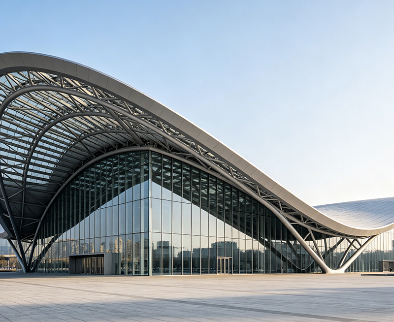
| Steel space frame | Stadiums, terminals, and exhibition halls | Three-dimensional strength and flexible roof shape | Higher connection and installation coordination |
| Arch structure | Sports halls and special architectural projects | Good visual form and efficient compression action | Large horizontal support forces may affect foundations |
| Cable-supported roof | Very large open spaces | Low self-weight and long coverage capability | High design, tensioning, and maintenance requirements |
How span length affects the decision
For spans around 30 to 50 meters, a portal frame or roof truss may provide a practical balance of cost and speed. From 50 to 100 meters, a deeper truss, tied arch, or space frame often becomes more efficient. Beyond 100 meters, designers may study a space frame, cable system, arch, or hybrid structure.
These ranges are early planning guides, not final rules. A local structural engineer must confirm the system after reviewing loads, support conditions, deflection limits, and construction access.
3. Control Strength, Deflection, and Stability Together
A steel member can be strong enough but still unsuitable if it bends too much. Large roofs are sensitive to serviceability problems because small movement can damage cladding, windows, drainage, ceiling panels, and equipment.
Strength checks
Engineers check tension, compression, bending, shear, and combined forces. They also check local buckling of plates and global buckling of columns, rafters, and truss members. Slender compression members need bracing at the correct spacing.
Deflection and vibration checks
Roof deflection limits depend on the cladding type, drainage design, ceiling system, and building use. A sports hall may also need vibration review from crowds, moving equipment, or wind. The final limit should follow the governing building code and project specifications.
Important conclusion: Increasing member size is not always the most efficient solution. Adding lateral bracing, improving the roof diaphragm, reducing unbraced length, or changing the structural layout can improve stability with less steel.
4. Design Connections for Real Construction Forces
Connections transfer forces between beams, columns, trusses, bracing, and foundations. In a large span steel building, connection design can control both safety and project cost. A connection that looks simple in a drawing may be difficult to weld, transport, or install on site.
Bolted and welded connections
Shop welding gives controlled quality and accurate alignment. High-strength bolted connections are usually preferred for field assembly because they reduce site welding and shorten installation time. The design should define bolt grade, hole type, tightening method, weld size, access space, and inspection level.
Moment, shear, and pinned behavior
A connection must behave as assumed in the structural model. If the model treats a joint as pinned but the detail transfers significant moment, the building may respond differently from the design. Gusset plates, end plates, base plates, stiffeners, and anchor bolts must all be checked as a complete load path.
For export projects, Jin'an Group coordinates connection drawings with fabrication and shipping limits. This helps prevent oversized assemblies that cannot fit into containers or cannot be lifted safely at the job site.
5. Consider Wind, Seismic Action, and Roof Drainage
A large roof has a wide exposed surface. Wind can create both downward pressure and uplift. Edge zones and corners often receive higher suction than the center of the roof, so purlins, roof panels, fasteners, and bracing need local checks.
Wind load path
Wind forces move from roof cladding to purlins, then to rafters or space frame nodes, columns, foundations, and soil. Every link must be strong enough. Missing roof bracing or weak cladding fasteners can interrupt this load path even when the main frame is strong.
Seismic behavior
In seismic regions, a lighter steel structure can reduce earthquake force, but only if it has a clear and ductile load path. Braced frames, moment frames, diaphragms, collectors, and foundation anchors must work together. Flexible equipment and suspended systems also need restraint.
Rainwater and ponding
Low-slope roofs require careful drainage. If water collects in a deflected area, its weight increases the deflection and may create more ponding. Designers should set roof slopes, gutter capacity, overflow paths, and emergency drainage before finalizing the frame.
6. Plan Fabrication, Transport, and Erection at the Design Stage
A design is successful only when it can be manufactured and installed safely. Design for manufacture and assembly reduces rework, field cutting, welding, and delays. It also makes the final price more predictable for overseas buyers.
Large span steel structure project flow chart
- Step 1: Confirm site data, building use, span, loads, codes, and soil conditions.
- Step 2: Compare portal frames, trusses, space frames, arches, or hybrid systems.
- Step 3: Build the structural model and check strength, deflection, buckling, and vibration.
- Step 4: Complete connection design, member schedules, bracing plans, and foundation reactions.
- Step 5: Divide the structure into transportable assemblies and confirm lifting points.
- Step 6: Produce shop drawings, cutting lists, welding procedures, and inspection plans.
- Step 7: Fabricate, blast, paint or galvanize, mark, pack, and inspect each component.
- Step 8: Erect columns, primary frames, bracing, secondary steel, cladding, and services in sequence.
- Step 9: Check bolt tightening, alignment, coating repair, drainage, and final safety records.
Transport and lifting limits
The design team should review container dimensions, road restrictions, port handling, crane capacity, and local access. A 12-meter assembly may need to be split into shorter pieces if the destination road network cannot carry it. Splitting pieces adds joints, so the cost and engineering effect should be compared before production.
Temporary stability during erection
A completed frame may be stable while a partly erected frame is not. Temporary cables, props, guy wires, and erection bracing may be required until the roof diaphragm and permanent bracing are complete. The erection sequence should appear in the method statement, not remain an informal site decision.
7. Select Materials and Protection for the Service Environment
Material selection affects strength, welding quality, durability, and total maintenance cost. Common structural steel grades can work well, but the correct grade depends on temperature, thickness, impact requirements, weldability, and local standards.
Corrosion protection
Indoor dry warehouses may use a paint system with standard surface preparation. Coastal, humid, chemical, or livestock environments need stronger protection. Options include multi-layer paint, hot-dip galvanizing, weathering steel where suitable, or a combined system. The specification should state surface preparation grade, dry film thickness, repair method, and inspection frequency.
Fire performance
Fire protection may include intumescent paint, cementitious spray, board systems, or a combination. The required fire rating depends on building height, occupancy, escape design, local code, and fire risk. Fire protection adds weight and affects connection details, so it should be included before final member selection.
Comparison: Lower Initial Cost or Lower Total Project Cost?
Overseas buyers often compare quotations by steel weight alone. This can lead to an incorrect decision. A lighter design may need more complex connections, special transport, difficult erection equipment, or expensive maintenance.
| Comparison factor | Low initial price approach | Value-focused approach |
|---|---|---|
| Steel quantity | Uses the lowest calculated weight | Balances weight with fabrication and erection cost |
| Connections | May require complex site work | Uses repeatable details and shop fabrication |
| Transport | Considers shipping after design | Plans piece sizes before shop drawings |
| Coating | Uses basic protection for all environments | Matches coating life to humidity and corrosion risk |
| Installation | Leaves sequence to the site team | Includes lifting, temporary bracing, and inspection plans |
| Future operation | Focuses on delivery price | Includes drainage, maintenance, expansion, and repairs |
What Information Should You Request from a Steel Structure Manufacturer?
Before approving a supplier, request more than a commercial quotation. Ask for the design basis, governing code, load assumptions, structural system, member grades, connection method, coating specification, quality plan, and estimated delivery schedule.
You should also request general arrangement drawings, column reactions, foundation loads, packing details, erection instructions, and a list of items supplied by others. These documents help the foundation contractor, cladding installer, crane operator, and local engineer coordinate their work.
A capable supplier should explain which parts are included in the scope. For example, steel frames, purlins, bracing, bolts, roof panels, wall panels, gutters, doors, windows, fire protection, and installation supervision may be priced separately.
Final Answer: The 7 Design Rules That Protect Your Investment
- Start with accurate site, load, soil, and building-use data.
- Select the structural system according to span, function, cost, and erection limits.
- Check strength, deflection, buckling, vibration, and stability as one system.
- Design connections for the real forces and the real construction method.
- Provide a continuous load path for wind, seismic action, snow, and equipment loads.
- Plan fabrication, transport, lifting, temporary bracing, and inspection before production.
- Match material grade, corrosion protection, fire resistance, and maintenance to the site.
Large span steel structure design is a coordinated engineering process, not a simple member-sizing exercise. When the structure, connections, materials, transport plan, and erection sequence are developed together, a 30- to 100-meter clear-span building can achieve reliable performance and controlled project cost. Jin'an Group supports overseas buyers and distributors with coordinated steel building solutions from design review through fabrication and delivery.